Why IR sensor
- Because it have good range which is fulfill our requirements for robots
- It is very low cost and can be constructed on general purpose PCB
- It is of very small size. which is best for robots
- You can increase numbers of transmitter as you want for good result
- Good immunity to ambient light and waves are invisible to eyes.
How it is work
Here in this sensor we connect IR receiver in reverse bias so it give very high resistance if it is not exposed to IR light. the resistance in this case is in range of Mega ohms.
but when IR light reflected back and fall on IR receiver. The resistance of Rx it comes in range between Kilo ohms to hundred of ohms.
We convert this change in resistance to change in voltage . Then this voltage is applied to a comparator IC which compare it with a threshold level (defined by us according to required range and sensitivity ).
if voltage of sensor is more than threshold then output is high else it is low (depends on your connection to comparator ) which can be used directly for microcontroller.
IR transmitter and receiver

IR LED is used as a source of infrared rays. It comes in two packages 3mm or 5mm. 3mm is better as it is requires less space.
IR sensor is nothing but a diode, which is sensitive for infrared radiation. This infrared transmitter and receiver is called as IR TX-RX pair.
It can be obtained from any decent electronics component shop and costs less than 10Rs. Following snap shows 3mm and 5mm IR pairs. Colour of IR transmitter and receiver is different.
However you may come across pairs which appear exactly same or even has opposite colours than shown in above pic and it is not possible to distinguish between TX and RX visually. In case you will have to take help of multimeter to distinguish between them.
How to identify IR Tx and Rx
- Connect cathode of one LED to +ve terminal of DMM
- Connect anode of the same LED to common terminal of DMM (means connect LED such that It gets reverse biased by DMM )
- Set DMM to measure resistance upto 2M Ohm. Check the reading.
- Repeat above procedure with second LED.
- In above process, when you get the reading of the few hundred Kilo Ohms on DMM, then it indicated that LED that you are testing is IR sensor.
- In case of IR transmitter DMM will not show any reading.
But there is a simple way to identify Tx and Rx by connect to supply. Connect +ve to 5volt and -ve to GND with a series resistor around 330Ohms or higher. Then look both through us a camera of mobile. One which glowing is transmitter.
Sensor Circuit
click to zoom
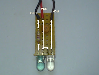
Solder Tx and Rx on a zero PCB and connect these three wire. which you can connect to comparator and mount this sensor any where on robot.
You can solder Tx and Rx like this
Now it time to connect output of sensor to comparator to complete our sensor. I use LM324 comparator while making this you can which you like. but LM324 have 4 comparator in one IC so you can connect 4 sensor using a small size PCB with one LM324.
This is connection of sensor output to comparator. -ve terminal have a potentiometer which use to set threshold level (range and sensitivity)
sorry for image error: it is DMM not DMC
Comparator LM324
this is specially for you if you don't know how a comparator work else you can skip it. comparator have a internal circuit which compare two input. one is called +ve and second is -ve. when you give +ve terminal voltage higher than -ve terminal voltage then the output of comparator is Vcc (supply voltage to IC). and if -ve voltage higher than +ve voltage then output is -VEE ( zero volt in our case ).
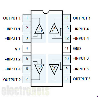
This is pin diagram of LM324
please share and give +1 if you like this tutorial. leave comment if facing any problem, follow us on fb and G+.....


Hey Nice Blog ..
ReplyDeleteContinue
thanx bro....
ReplyDeleteHi
ReplyDeleteIt's very nice, but I'm missing a second part of it ;-). For somebody like me, a novice in electronics it looks like you stopped explaining half way.
What do I do with the outut of the comparator?
Pitty, you don't explain what the C1 is for and what makes the sensor immune to, if at all, to other infrared sources.
@Anonrate: use of comparator depend on your requirement,may be you are making a line follower or a object counter.
ReplyDeleteC1: here no major role of c1, it will work without it. but it provide filtering and from where you not understand.
thanx
thank you... I gained some knowledge about ir lLEDs..
ReplyDeletewhat is the serial no of this ir sensor pair....... i need it for obstacle detection,,....?\
ReplyDeleteI think there is no serial number, go to shop and ask him for 5mm IR pair. he will give you this one.
ReplyDeleteBecause it have good range which is fulfill our requirements for robots.
ReplyDeleteBecause it has good range which is fulfill our requirements for robots.
Note from have to has.
why r u using potentiometer at the output of the sensor which is going into the voltage comparator ic
ReplyDeletewhat is 55% in potentiometer
ReplyDelete@abpccpba - thanx for your suggestion
ReplyDelete@nirav - it is showing that value of potentiometer = 55% of max
@muhammad - (+) of Comparator read the voltage drop across potentiometer when current increase due to forward bias of IR. so you can change the sensor output voltage by changes its value.
Very Detailed explanation.. Helped a lot.. Thank You... ! :)
ReplyDeleteWelcome buddy..
ReplyDeletehi mr. Natwar
ReplyDeletei would have some problem of the IR, when i try it, i measured the voltage, no matter how near the IR and to the flat surface, but still same voltage from Vout, so how did i solve the question i solved, i only end without comparator and the var resistor
@kelvin: you mean Sensor output (not comparator output) remain same. then may be problem in your IR Rx. did you check IR pair. may be it is a IR Tx. change your var-resistor, the voltage must change. change your cap. try these solutions it must work for you.
ReplyDeleteWhat is the need of the capacitor in the circuit....??????
ReplyDeletemany circuits don't show the capacitors involved...
i've used two resistor as in the standard circuit ..... but the output is not stable...
ReplyDeletei've used this circuit:http://fatimahhusin.files.wordpress.com/2008/08/ir_proximity_sensor.jpg
LM 324 is a comparator or opamp? And can I use LM 339 instead of 324?
ReplyDelete@Kuldeep: There are couple of ckt to design it. but some time output signal is very low. This circuit is tested my me. It will give range of around 10 cm.
ReplyDelete@Rstorm: Here Comparator and Opamp are used for same purpose. so you can any other variant of it.
What kind of filter the capacitor C1 does?
ReplyDeleteWhat kind of Capacitor is more effective in this stage?
If you have any reference about it please give me......
i want to know details on it......
what is the range IR sensor ?
ReplyDeletehow many types of IR sensor ?
ReplyDeletevery clean and neat explanation
ReplyDeletegreat write up! thank you
There are times when people are having lots of trouble while they are planning to download aol gold desktop in their computer. If you are also one of them, you need first to see whether your system is fulfilling all the requirement which is required for downloading the software.
ReplyDelete