 |
finding some parts in multisim is really tough work because multisim not provide all general purpose component like 7085 and other voltage regulator. one more bad information is that manufacturer of these component also not provide any PSPICE because output of these component are predetermined and not changed according to the circuit.
I also tried too much on internet and in multisim component database to get ICs like this earlier , Because these used in each project. But i get these after working some months with multisim. So instead getting replacement of 7805 we are going to create it.
First Method:
one solution is that i use a Three Pin Connector and use it according to my own assumption of pins working (in real they work nothing).
But what about its footprint because connector's footprint is not same as a 3 pin voltage regulator. The solution of this is that i change the holes location of connector's footprint according to dimension of original 7805 by using this yellow highlighted button.
My design looks like this ( it is only an example ) "click on any image to zoom"
  |
| click to zoom |
Second Method:
The second and best solution is that we make a new component. which can be used without changing any time.
note: here we are making component for footprint only not for simulation
Step 1:
goto menu tools>component wizard and click in multisim design
a dialog box appear to fill some detail
Step 2:
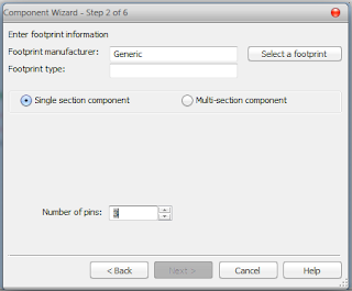
click on next and choose single section component, no. of pins=3 and click on "select a footprint"- select "master database" at Database name and click on "Filter" button
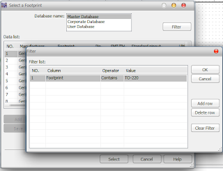
- a new box appear click on "Add row" button ( a new filter condition added )
- select "footprint " in Column, "contain" in Operator and type "TO-220" in Value.
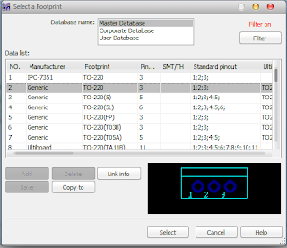
why TO-220: because each component have one or more package type and 7805 have "TO-220"
(look in data sheet)
you get many footprint in select a footprint window and select second footprint
Step 3:
click on next, you get new window in which a symbol is show with ANSI selectedhere you can edit you component or you can use as shown
after little editing my component look like some thing like this
( To edit: click and drag your pins where you want to place in you design )
after editing
Step 4:
you can leave this as comes but if you want to change you can use as showStep 5:
select pins as shown by clicking in "Footprint pins"Step 6:
click on user database > add family > type family name"regulator"> finisha new family added in user database with name regulator
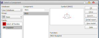
and finally we make a new component you can get this by selecting "user database" in "select a component"
if you face any problem feel free to use comment box.
please share the post if it help you a little and give a +1, thanx for reading


I had exactly the same problem... Couldn't find the 7805CV, as I'm a new user I didnt know multisim yet. I thank you very much for your post ! It worked like a charm.
ReplyDeleteI had to search a while when I was editing the symbol to get the numbers placed right. Especially with the resizing of the rectangle. Be sure to RESIZE BOUNDARY BOX or you will be stuck with pins being placed out of the new size.
thanks for considering it useful. you are right about editing symbol, it takes time to get familiar with symbol editor. Try each tool you get what they exactly does. thanx..
ReplyDelete